

1. Introduction
2. Assessment of the effects of rib reinforcement using large-sized model tests
2.1 Conditions of large-sized model tests
2.2 Experimental results
3. Appropriate model for rib reinforcement
3.1 Design of vaults with rib reinforcement
3.2 Model tests for selecting the appropriate type of rib reinforcement
4. Conclusions
1. Introduction
The construction method for cut-and-cover tunnels is determined by several factors, including site conditions, construction feasibility, and economic efficiency. In Korea, the cast-in-place method is generally used. However, this method requires a reinforcing rod assembly, a steel mold installation, placing of concrete, and curing; it is also not applicable in every situation, and quality control of the concrete is difficult. To solve the problems of the cast-in-place method, precast segments can be used efficiently for cut-and-cover tunnels (Lee et al., 2008). Dividing the concrete lining into precast segments allows its thickness to be reduced, because the bending moment is decreased by the connecting parts between the segments effectively acting as hinges (Bae et al., 2002). Several studies have analyzed precast cut-and-cover tunnels both experimentally and numerically. Saitoh et al. (1998), Kawamura et al. (1998) experimentally studied a double-hinged arch culvert tunnel using a 1/2 scale model subjected to static-cyclic horizontal loading tests. Adachi et al. (2001) experimentally investigated the mechanical behavior of a single type of cut-and-cover tunnel structure with a filled embankment. To suggest a reasonable modeling technique of the precast segmented connecting parts of a waterway culvert structure, Lee et al. (2010) conducted field experiments and numerical analyses. Theoretical and experimental investigations by Campana and Muttoni (2010) suggested that a polygonal shape for cut-and-cover tunnels can combine the advantages of the classical vault and frame shapes. Hwang et al. (2005) simulated a multi-type cut-and-cover tunnel structure with filled embankments to examine the initial stress of the embankment ground. Sawamura et al. (2013) performed centrifuge model tests and numerical analyses to find the optimal spacing between the installed arch culverts and to clarify the interactive seismic behavior of the filling material and the multi-type culvert structure.
2. Assessment of the effects of rib reinforcement using large-sized model tests
2.1 Conditions of large-sized model tests
2.1.1 Preparation of test specimens
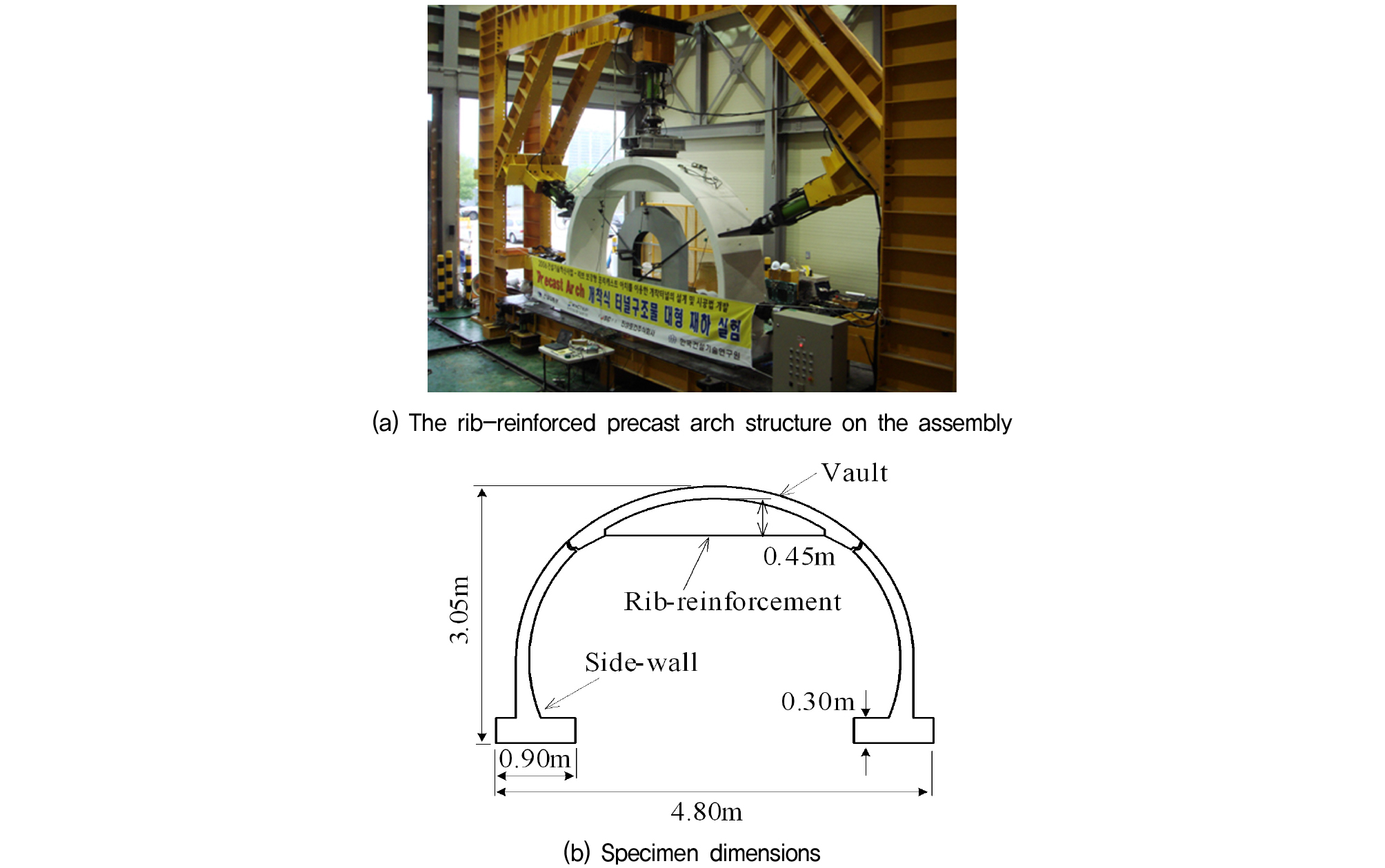
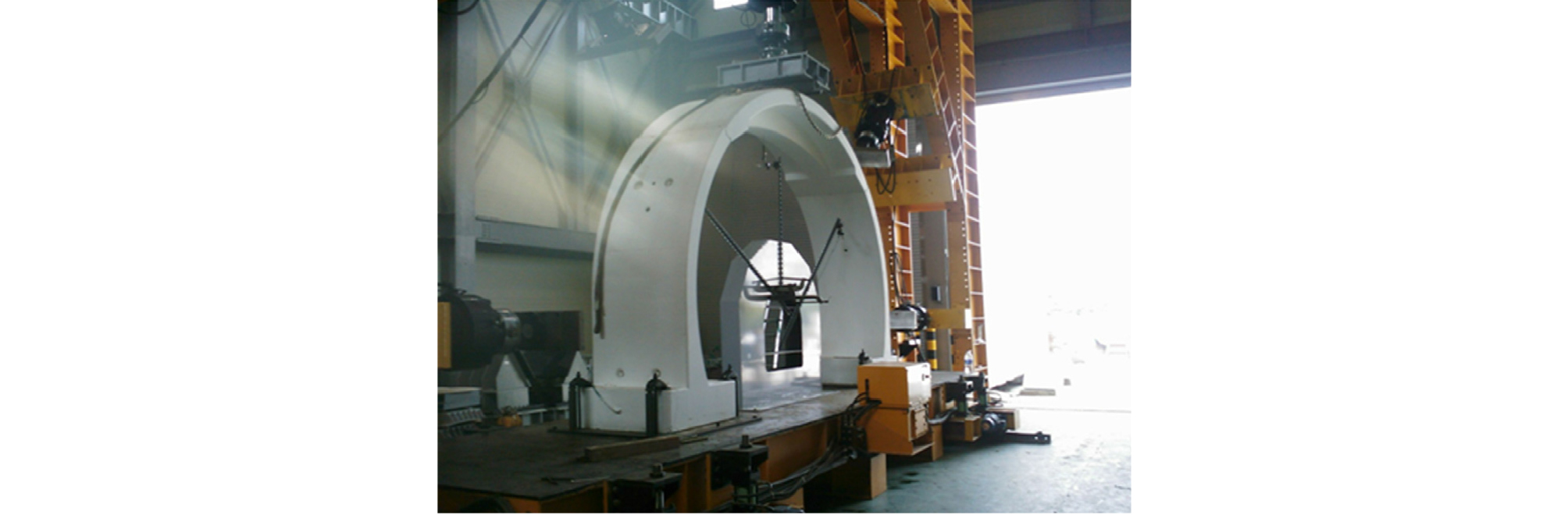
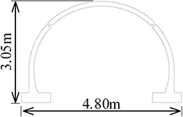
The indoor tests used 1/2.667 scale reduction model specimens (width 4.8 m, height 3.05 m). Satisfactory reproduction of the behavior of full-scale structures by the models requires similarity conditions to be met. These conditions can be divided largely into geometric, material, and load similarities. Geometric similarity can be met by reducing all the specifications of a structure proportionally to the ratio of similarity. However, as we could not find an identical product to the rebar used for the rib-reinforcing, we chose that which most closely matched this requirement. However, as the number of rebar decreased, the spaces between the rebar arrangements become wider, even though the steel ratio remained similar. Although the shape of the crack is somewhat different for a specimen prepared in this way, we judge it sufficient for reproducing the overall behavior of a full-scale structure. To analyze the effects of rib reinforcement on precast cut-and-cover tunnel segments, specimens were prepared with and without rib-reinforcement.
2.1.2 Loading tests
To simulate the confining effect of the embankment on the tunnel structure, the sample was confined at four points during the load testing (Fig. 2). A linear load was exerted on the crown via a servo-controller. Loading progressed at 19.62 kN/min.

2.1.3 Measurements
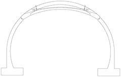
Loads were measured at points on the each structure 0.64 m and 1.79 m above the ground on the inside and the outside of the arch. To analysis bending moment, axial force, the rib-reinforced structure had twelve strain gauges installed at six places, including at two places in the lower middle part of the rib.
2.2 Experimental results
Loading tests were performed on the simple arch structure with no rib reinforcement, and on the arch structure with rib reinforcement. The points of confinement were 0.64 m and 1.79 m above the base, on the exterior surface of each side of the side wall segment; these locations are coincident with the measurement locations. These points of confinement elicit a response similar to that obtained under actual filled conditions, as determined by finite-element analysis.
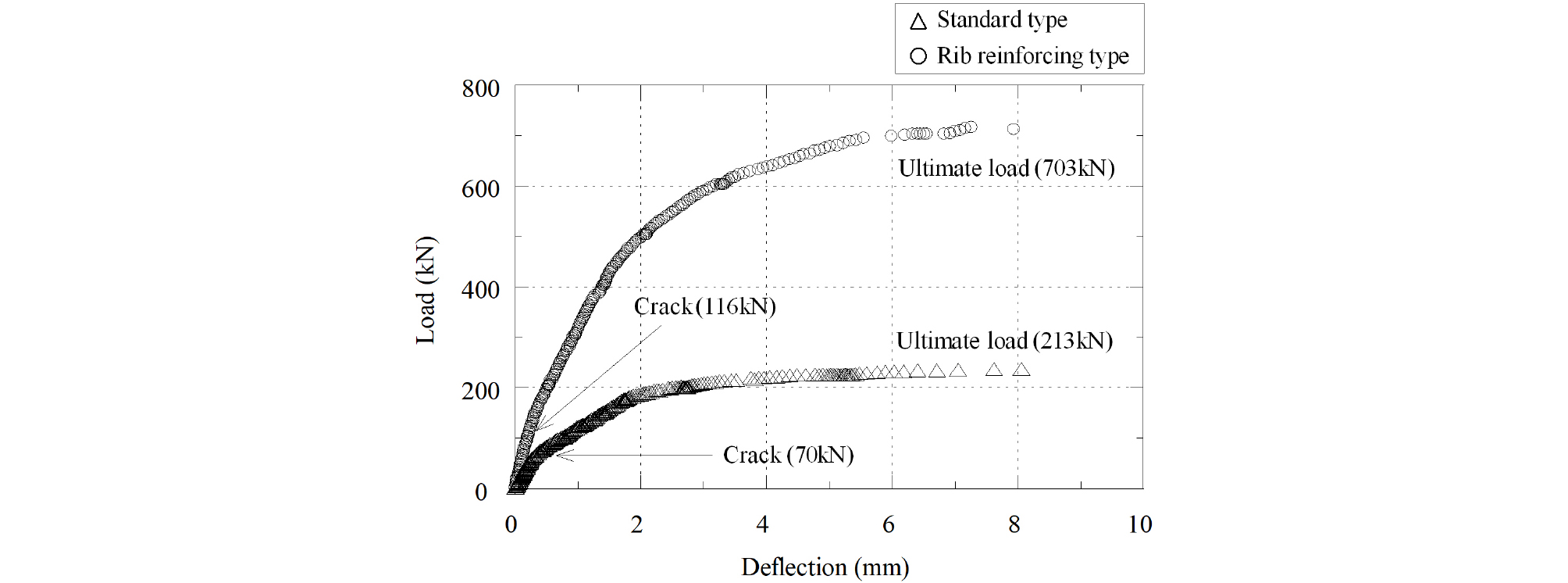
Therefore, the behavior modeled here will closely represent that of the completely constructed and filled structure. The load-deflection relationship is shown in Fig. 3. The crack load of the standard specimen is 70 kN, and its ultimate load at destruction is 213 kN. The respective values for the rib-reinforced arch structure (116 kN and 703 kN) are 1.7 and 3.3times those of the standard sample under the same confining conditions.
The load-strain relationships for the two samples are shown in Fig. 4. Pre-cracking compression in the standard arch structure occurred in the upper reinforcing rod of the arch segment. However, the lower reinforcing rod showed almost no deformation due to the confinement of the upper part of the side wall segment. A load of 70 kN was sufficient for the neutral axis to crack in the lower-middle section of the crown, the part under tension.
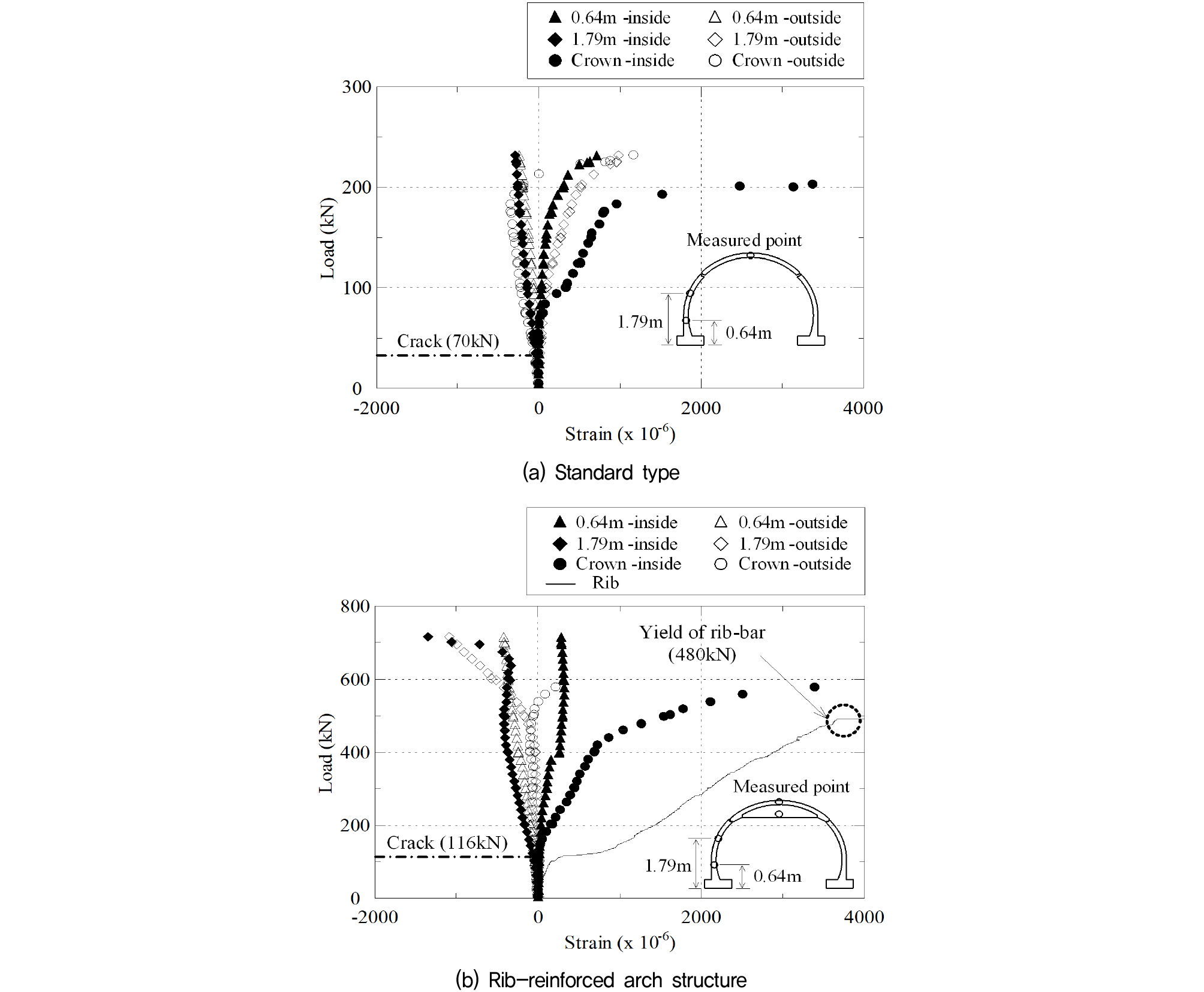
However, given it was considerably suppressed by the confining effect, compression in the upper rebar and tension in the lower rebar were observed up to a loading of about 200 kN, unlike the other non-rib-reinforced specimens. As the load exceeded 200 kN, the rebar in the lower-middle part of the crown yielded. Tension simultaneously occurred on the upper side the rebar. Ultimately, the specimen was destroyed as the concrete in the compressed part was crushed. In terms of the overall behavior of the tunnel lining, compression occurred in the outer part, and tension occurred in the inner part due to the influence of strain control from the outer side around the piers of both sides. In the shoulder, there was tension on the outer side and compression on the inner side. Deformation was greater in the shoulder than in adjacent regions. Regarding the overall dynamic behavior of a completely constructed, standard arch-type cut-and-cover tunnel, deformation increased in the order of the crown, shoulder, and pier due to the upper loading of the filling.
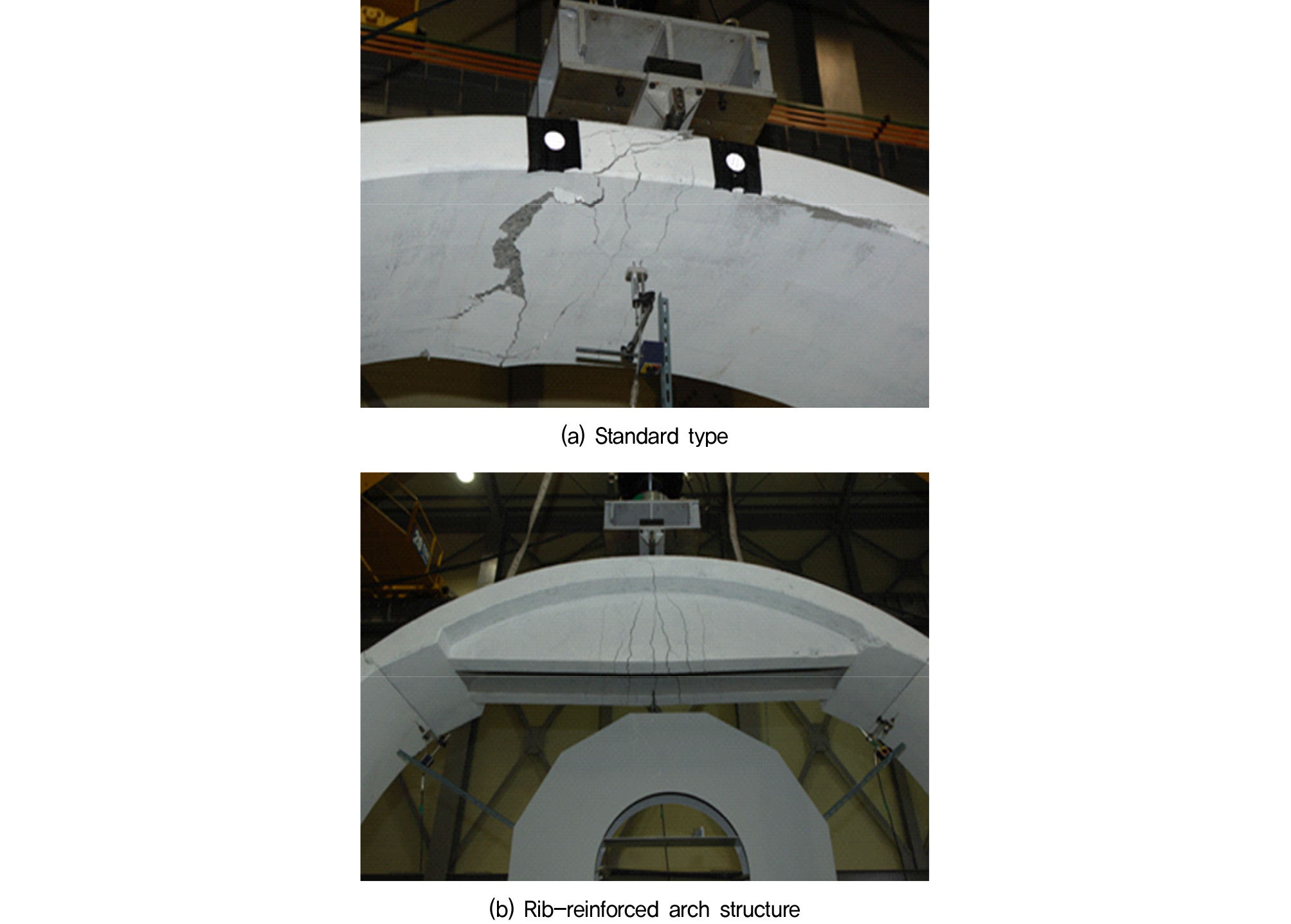
In the rib-reinforced arch structure, no deformation of the upper or lower rebar was observed prior to cracking, indicating the reinforcing effect of the rib. However, a load of about 116 kN induced a crack in the lower part of the rib center. Upon cracking, compression was observed in the upper rebar of the arch and in the loading phase, and tension was observed in the lower rebar as the neutral axis was raised as the crack progressed from the bottom of the rib-reinforcement. The rebar of the rib-reinforced part yielded at about 480 kN. With further loading, the slope of the load-strain plot rapidly decreased as the load burden in the lower rebar of the crown increased, finally arriving at the yield point with a load of about 600 kN. Tension was observed in the upper rebar, which finally yielded at 703 kN. In terms of the deformation of the rebar in the upper part of the crown, the overall behavior of the tunnel structure was minimal until the neutral axis had advanced to the upper part, as the rebar on the tension side yielded. Consequently, a relatively large deformation occurred at the pier and the shoulder. Fig. 5 shows the destruction caused to both samples during the loading tests.
The crack and ultimate loads (Table 1) of both specimens were obtained during the static loading tests. The load required to crack the crown of the reinforced segment was 1.7times that required to crack the standard section, and the ultimate load was 3.3times greater, demonstrating the strengthening effect of the rib reinforcement and its ability to improve the structural stability of tunnel structures comprising precast segments. Therefore, it would be applicable to the building of wide tunnels such as for high filling conditions or four-way road tunnels.
3. Appropriate model for rib reinforcement
3.1 Design of vaults with rib reinforcement
The above results demonstrate the improvement of the precast arch-tunnel structure by rib-reinforcement, as stiffening the arch-tunnel structure increased the ultimate load by about 3times. However, rib-reinforcement requires space within the tunnel section, which may unacceptably constrict the available space. A drawback of the above results examining the mechanical behavior of each tunnel segment is that they do not confirm the advantage of the arch structure in supporting the upper load and limiting deformation, because the rib reinforcement is structured such that all the load from above is concentrated on the arch structure.
In the model tests in this chapter, therefore, we attempt to assess the mechanical characteristics of the reinforcement by comparing several patterns of rib reinforcement and their effects on the arch structure.
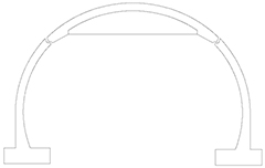
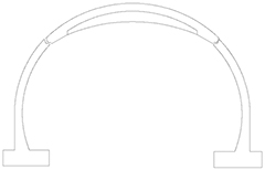
Table 2 depicts the various shapes of structure considered here, which include the two structures of the previous test (the standard type, Case-1, and simple rib-reinforced structure, Case-2) and also a structure with an arched rib-reinforced section (Case-3) and a structure (Case-4) with a prestressed rebar installed instead of the rebar arranged on the vault of Case-3. The size and specifications of the concrete structure are identical to those described in the previous chapter. The load was applied to a point at the center of the vault, and model tests were performed as before with confinement at points at the bottom and side walls, without full confinement of the sides.
3.2 Model tests for selecting the appropriate type of rib reinforcement
Figure 7 plots the relations between load and steel strain measured at points on the inside and the outside of each sample. Under the confinement applied to points on both sides of each structure, tension on the inside and compression on the outside were found in every case at 0.64 m above the lower section.
However, measurement at the shoulder, 1.79 m above lower section, found compression on the inside and tension on the outside for every case except Case-2. Although Cases-1, 3 and 4 showed different maximum deflections because of their different ultimate load they showed no difference in the speed of the deformation by loading. Accordingly, the results indicate that Cases-3 and 4 show the same basic behavior. In Case-2, tension occurred on the inside and compression occurred on the outside at both the shoulder and the bottom, indicating that the vault pressed on the sidewall vertically, causing large deformation at both the inside and the outside of the shoulder where the concrete was relatively thin.
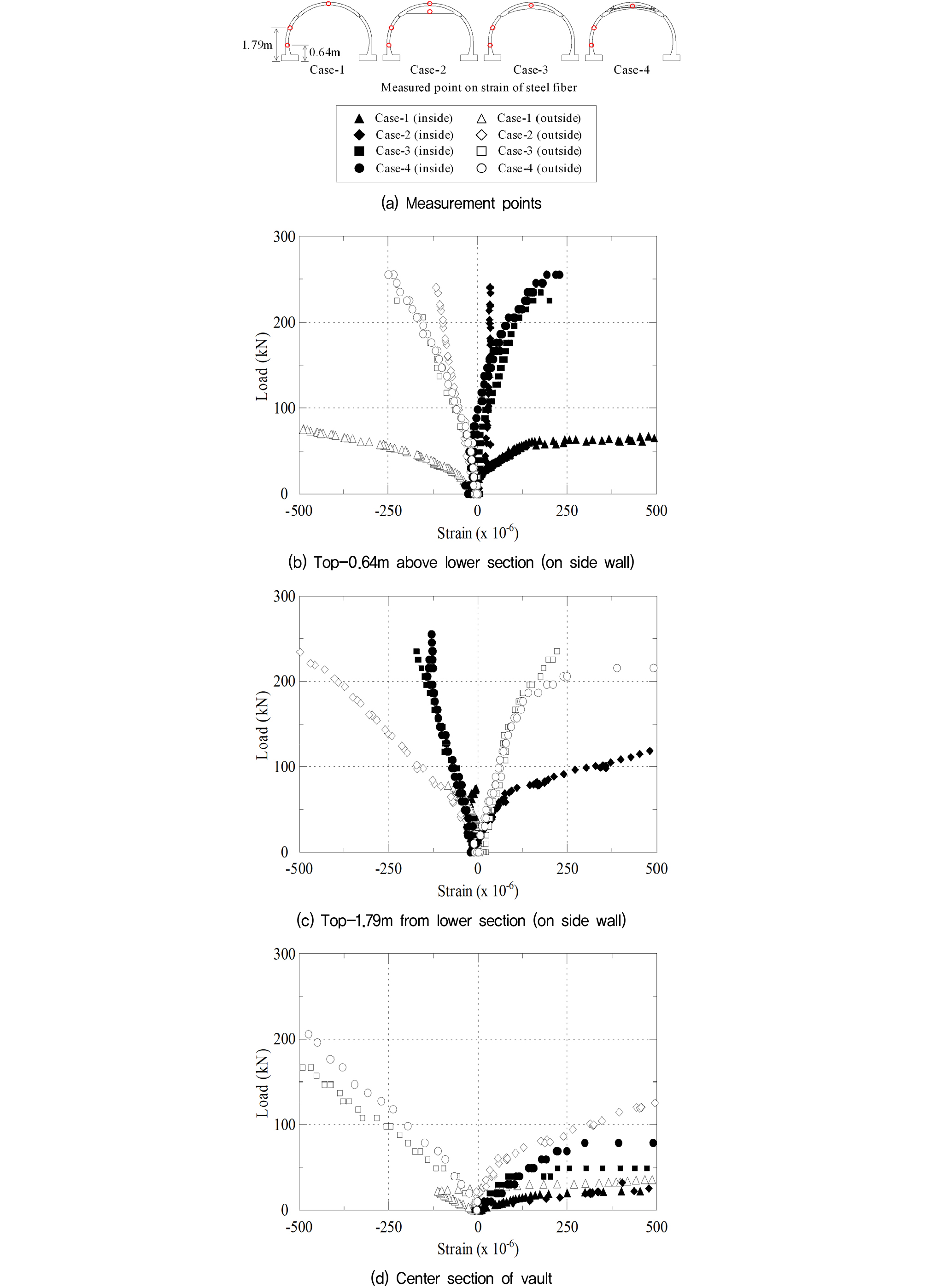
Figure 8 shows the load-strain relations for vertical displacement in each case, and Table 3 lists the crack and ultimate loads and the normalized rib effect (i.e., the ratio of the ultimate load of the rib-reinforced structure to that of the standard type). Similar tendencies to those in Fig. 4 emerge here. Case-2 behaves as a stiff structure while displaying considerably smaller displacement than Case-1. On the other hand, Cases-3 and 4 show displacements similar to Case-1, but their ultimate loads are about three times greater. The testing of Case-4 was interrupted by the separation of the vault and the sidewall at their connection at the right shoulder (Fig. 9); however, its ultimate load would likely be much greater due to the prestressing effect.
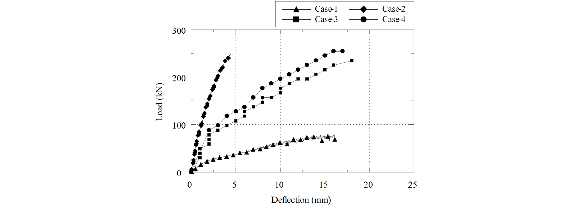
Table 3.
Crack loads and ultimate loads for various rib-reinforced tunnel segments
| Type | Crack load (kN) | Ultimate load (kN) | Normalized rib effect |
|
Case-1 Case-2 Case-3 Case-4 |
20.0 55.0 30.0 34.0 |
78.5 249.5 235.0 254.8 |
1 3.18 2.99 3.25 |
We judge that the lack of displacement control (i.e., side-wall filling) in this experiment exacerbated the problem of separation at the shoulder. However, the concrete should be confined with bending bolts to ensure that a structure in the field can safely withstand the influence of variations in the tunnel lining and ground vibration by differential settlement.
4. Conclusions
Rib-reinforcement of precast concrete arches for cut-and-cover tunnels was assessed via plate bearing tests using large-sized specimens of 1/2.667 scale based on a two-way road tunnel. The tests led us to the following conclusions. To simulate the confining effect of a tunnel structure by the embankment, the test specimens were confined at four places. The results showed that rib reinforcement increased the ultimate load of the structure by about 3.3 times relative to a non-reinforced sample. Comparison of vaults with various rib-reinforcement types showed that Cases-3 and 4 showed similar displacement behavior to the standard non-reinforced sample (Case-1), but showed about 3 times its ultimate load. The rib reinforcement greatly improved the structural stability of the precast tunnel segments, making the segments suitable for wide tunnels such as for high filling conditions or four-way road tunnels. Loading tests with miniature model specimens and static load tests with large-sizedspecimenshave provided sufficient data for the crack moment and the ultimate moment, respectively, to demonstrate that the design is safe enough for use regardless of whether rib reinforcement is used. Therefore, itis judged that it can be used for cut-and-cover tunnels.
