

1. Introduction
2. Numerical simulation of the centrifuge test
3. Parametric study
3.1 Flexibility-racking ratio relations
3.2 Effect of buried depth
3.3 Effect of aspect ratio
3.4 Proposed equations
4. Conclusions
1. Introduction
The tunnels play an important role in urban transport infrastructure. The tunnels are known to perform well during past severe seismic events (Arango, 2008; Dowding & Rozan, 1978; Hashash et al., 2001). However, damage to tunnels in recent earthquakes (Ghasemi et al., 2000; Iida et al., 1996; Wang et al., 2001) reminded that their seismic design should be considered carefully.
The seismic response of rectangular tunnels has been extensively studied including experiment test (Abate et al., 2015; Chen et al., 2014; Guoxing et al., 2015; Moghadam & Baziar, 2016; Tsinidis, 2017; Wang et al., 2018; Xu et al., 2016; Yan et al., 2016), numerical simulations (Abate & Massimino, 2017; Hashash et al., 2018; Lee et al., 2016; Nguyen et al., 2019a; Nguyen et al., 2019b; Nguyen et al., 2020; Sadiq et al., 2019; Sayed et al., 2019; Tsinidis, 2017; Wang et al., 2019) and analytical (Bobet, 2010; Bobet et al., 2008; Huo et al., 2006). Nonetheless, the results of those researches have not been widely applied in practice. Conventional design methods (Anderson, 2008; Hashash et al., 2001; Penzien, 2000; Pitilakis & Tsinidis, 2014; Wang, 1993) are still used due to their simplicity in implementation.
Wang (1993) proposed a simplified static frame analysis method for evaluation seismic response of the rectangular tunnels. The core of the method is to choose a relevant relation of racking ratio (R) with flexibility ratio (F) to calculate structure racking. R is defined as the ratio of the relative displacement between the top and bottom corners of the structure to the free field relative displacement. F represents the relative flexibility between the structure and the soil. The F-R relation suggested by Wang (1993) was obtained based on a series of dynamic analysis account for varies structure types, soil profiles, buried depths, and input ground motions. Penzien (2000) established F-R relational equations considering the effect of soil-structure interface condition and Poisson’s ratio by an analytical procedure. Anderson (2008) recommended a design racking curve by fitting the F-R results from numerical analyses. However, recent studies demonstrated that the deformation of rectangular tunnels during seismic shaking is not a pure racking but a coupled racking-rocking mode (Abuhajar et al., 2015; Cilingir & Madabhushi, 2011a, b; Tsinidis et al., 2015; Tsinidis et al., 2016). Tsinidis & Pitilakis (2018) developed a new set of F-Rm relations but nonlinear soil model and slip contact interface have not yet been investigated. Rm is defined as a modified racking ratio considering the effect of the rocking response. Furthermore, the constant shear wave velocity along with the depth in the study of Tsinidis & Pitilakis (2018) appears to be an unrealistic assumption.
The aim of this paper is to explore the relations between flexibility ratio and new racking ratio, developed for a wide range of soil-tunnel configurations. The relations account for the nonlinear behavior of the surrounding soil, and friction contact interface between soil-tunnel. The numerical model validated against centrifuge tests is used to perform a series of dynamic analyses. Furthermore, tunnel rocking response, the effect of buried depth and aspect ratio are examined.
2. Numerical simulation of the centrifuge test
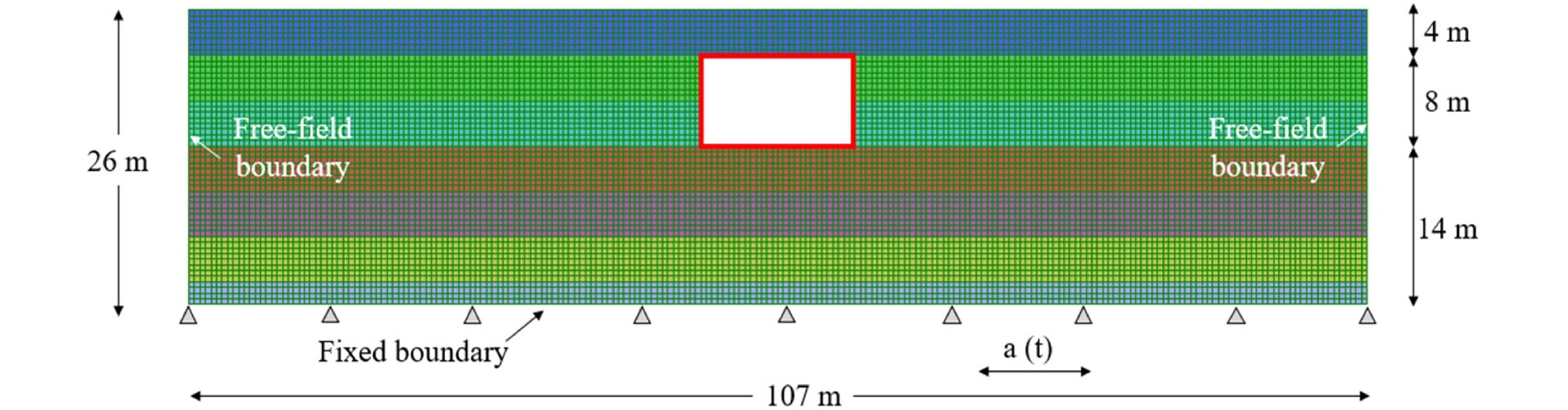
The tunnel and the surrouding soil was simulated by using a two-dimensional finite-difference analysis program FLAC2D version 7.0 (Itasca Consulting Group, 2011). The numerical model is presented in Fig. 1. The dimension of the computational model was set to 107 m and 26 m in width and height, respectively. The soil was modeled as a uniform, medium-dense sand.
The soil medium was modeled by using plane-strain quadrilateral elements. Element size, ∆l = 0.5 m was selected based on recommendations of Kuhlemeyer & Lysmer (1973):
where λ is the wavelength of propagated wave corresponding to maximum frequency interested. The Sig3 model was used to simulate the nonlinear behavior of soil. The model is available in FLAC2D program, widely used in previous studies (Callisto & Ricci, 2019; Lee et al., 2015; Lu & Hwang, 2017; Park et al., 2019; Sanderson, 2018), is defined as follows (Itasca Consulting Group, 2011):
where Ms is secant shear modulus reduction factor, L is log(γ), γ is the shear strain, and xo, a, and b are the parameters of curve-fitting. The parameters of the Sig3 model were selected to match the curves of Darendeli (Darendeli, 2001) and then strength-corrected at the middle of each soil layer. The parameters used to generate the shear modulus reduction and damping curves with the Darendeli formulation are listed in Table 1.
Table 1.
Input parameters for Darendeli (2001) formulation
| Parameter | Assumed value |
| Lateral at-rest earth pressure coefficient (K0) | 0.46 |
| Plastic index (PI) | 0 |
| Over consolidation ratio (OCR) | 1 |
| Excitation frequency | 1 |
| Number of cycle loading | 10 |
The Rayleigh damping was used to model small strain damping, is expressed as follows (Chopra, 2001):
where [C] is the damping matrix, [M] is the mass matrix, [K] is the stiffness matrix, α and β are the Rayleigh coefficients which is determined through:
where ξ is the damping ratio, fm and fn is the natural frequency at mth and nth modes, respectively. The Rayleigh coefficients α and β should be selected to minimize the frequency dependence of damping (Kwok et al., 2007). Kwok et al. (2007) recommended using 1st and 5th modes frequency for fm and fn, respectively. In this study, 1st and 5th modes were used for soil layers.
The tunnel is embedded at a depth of 4 m from the surface. The height of the tunnel is fixed to 6 m, whereas the width is varied from 6 m to 18 m. The deails of the dimensions are provided in the next section. The tunnel structure was simulated by using beam elements with 0.5 m of the element size. The input parameters used for structural elements are listed as designed target properties in Table 2.
Table 2.
Properties of tunnel structure models (Gillis, 2015)
| Parameter | Property |
| Wall, slab thickness (m) | 0.8 |
| Density (kg/m3) | 2,400 |
| Young’s modulus | 2.50 × 10⁷ |
| Poission’s ratio | 0.2 |
The soil-structure interaction was simulated by using the interface elements. The interface option UNBONED in FLAC2D program was used in this study. This contact interface allows the gap and the slip between soil and tunnel under loading. Parameters for the interface element include normal and shear springs stiffness (Kn and Ks). As recommended in FLAC2D manual (Itasca Consulting Group, 2011), Kn and Ks are calculated as follows:
where K and Gmax are the bulk and shear modulus of the stiffest neighboring zone, respectively, and ∆Zmin is the smallest width of an adjoining zone in the normal direction. The max [ ] notation implies that the maximum value over all zones adjacent to the interface. Using properties of the tunnel material as the stiffest neighbor zone in equation (5), Ks and Kn value are greater than 1011 Pa/m. A large value of Ks and Kn should not be used due to increased analysis time (Itasca Consulting Group, 2011). Therefore, the obtained values of Ks and Kn are reduced to 1010 Pa/m in this study (Baziar et al., 2014). This reduction does not significantly affect the results whereas analysis time dramatically shortened. Properties of the interface elements are considered in Table 3.
Table 3.
Interface element properties
| Parameters | Value |
| Normal stiffness, Kn (Pa/m) | 1010 |
| Shear stiffness, Ks (Pa/m) | 1010 |
| Friction angle (degree) | 33 |
The free-field boundary was applied for lateral boundaries to absorb reflected waves. The bottom boundary was fixed to simulate the rigid boundary used centrifuge test. The input ground motion used in this analysis were described in the previous section.
3. Parametric study
A series of dynamic analyses were performed by using the numerical model with different soil-tunnel configurations to develop a set of F-R and F-Rm relations. The dimensions of the rectangular tunnel cross-sections were varied such that aspect ratio (width (B)/height (H)) ranging from 1 to 3. A center column was considered for the tunnel that the aspect ratio greater than 2 to match the common static design. The lining thickness of the slab, wall, and center column was assumed to be similar to all structural elements. Furthermore, it was varied to obtain a set of F from rigid to flexible tunnel (i.e. F = 0.1, 0.2, 0.5, 1, 2, 5, 10) for each soil-tunnel configuration. The investigated tunnel structures are shown in Fig. 2. Three buried depths (h = 3, 6, and 12 m, corresponding to buried depth ratio (h/H) = 0.5, 1, and 2) were used to represent for cases of the shallow and deep tunnels.

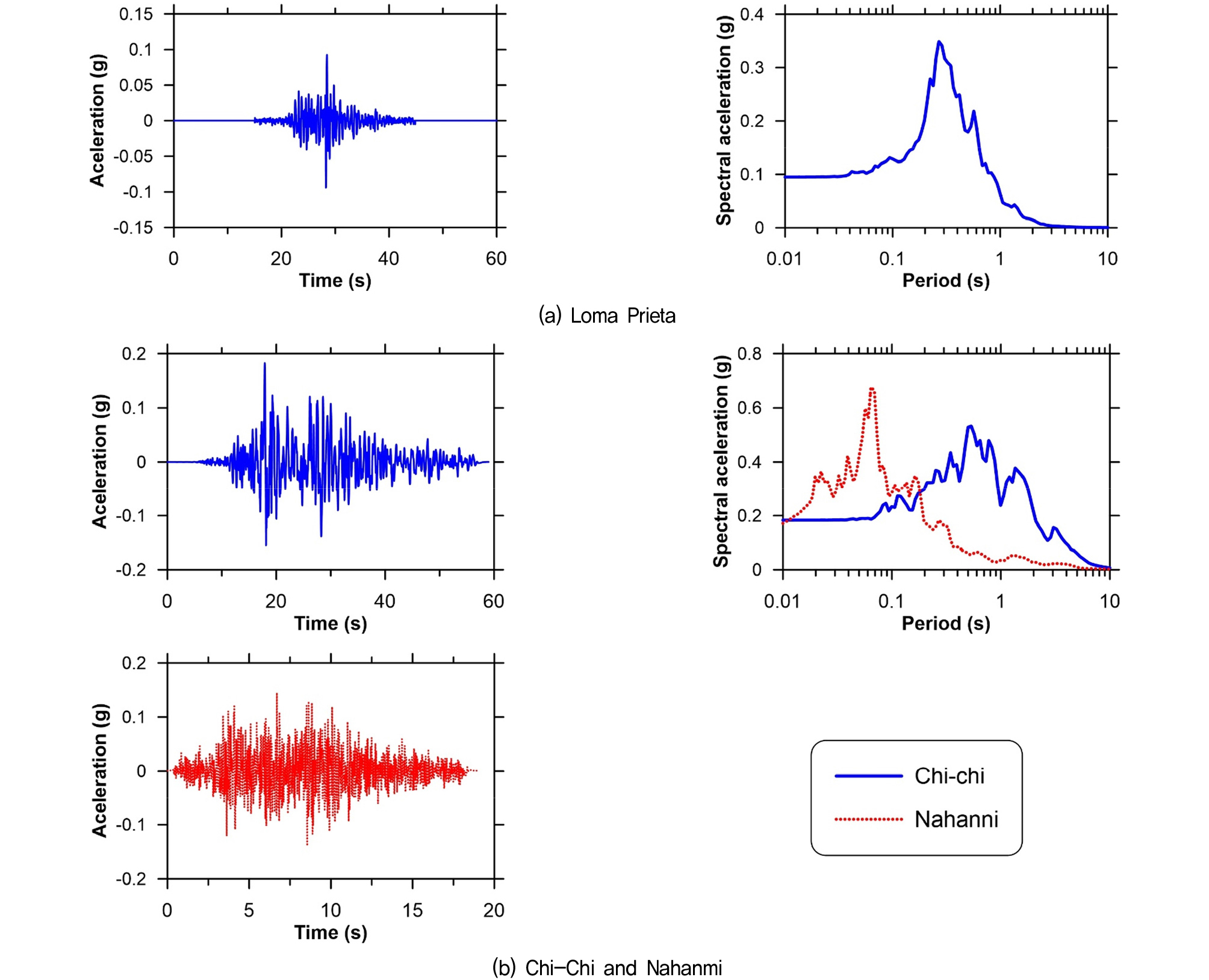
Two shear wave velocities (Vs) profiles were used, as shown in Fig. 3. The unit weight of soil was set to 15.3 kN/m3. Three motions were used, as listed in Table 4. The acceleration time history and response spectra are shown in Fig. 4.

Table 4.
Characteristics of additional input motion for parametric study (Sadiq et al., 2019)
| Event | Station | Year | PGA (g) | Tp (s) | Ia (m/s) | D5-95 (s) |
| Loma Prieta | Santa Cruz | 1989 | 0.1 | 0.1 | 11.3 | 0.6 |
| Chi-chi | CHY-047 | 1999 | 0.18 | 0.54 | 1.1 | 34.9 |
| Nahanni | Site 3 | 1985 | 0.17 | 0.06 | 0.2 | 6 |
3.1 Flexibility-racking ratio relations
Based on the results of the parametric study, a set of flexibility-‘original’ racking ratio (F-R) and flexibility-modified racking ratio (F-Rm) were developed and compared with each other in this section. As can be seen from Fig. 5, R is computed as follows (Wang, 1993):
where ∆s and ∆ff can be determined as relative horizontal displacements of tunnel and free-field at elevations corresponding to the top and bottom tunnel levels, recorded and computer during analysis.
The modified racking ratio, Rm, which consider the effect of rocking rotation, is obtained by:
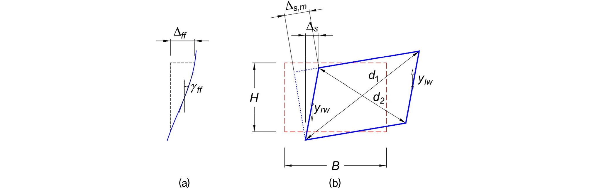
where ∆s,m is actual structure racking and calculated as follows (Nishioka & Unjoh, 2000; Tsinidis & Pitilakis, 2018):
d1 and d2 are the lengths of two diagonal edges of the deformed tunnel section at the maximum distortion time step during ground shaking.
The flexibility ratio, F, is determined as (Wang & Munfakh, 2001):
where Ks is the racking stiffness of the tunnel, obtained by applying a unit lateral force at the roof of the structure while restraining the base divided by the resulting lateral displacement. Gm is the strain-compatible shear modulus of the surrounding ground, calculated by using the following equation (Gillis, 2015):
where γeq and γff is the equivalent and maximum free-field shear strain at mid-height of the tunnel level depth. The maximum free-field soil shear strain was estimated during each motion by dividing the corresponding maximum racking displacement by the structure height (γff = ∆s/H).
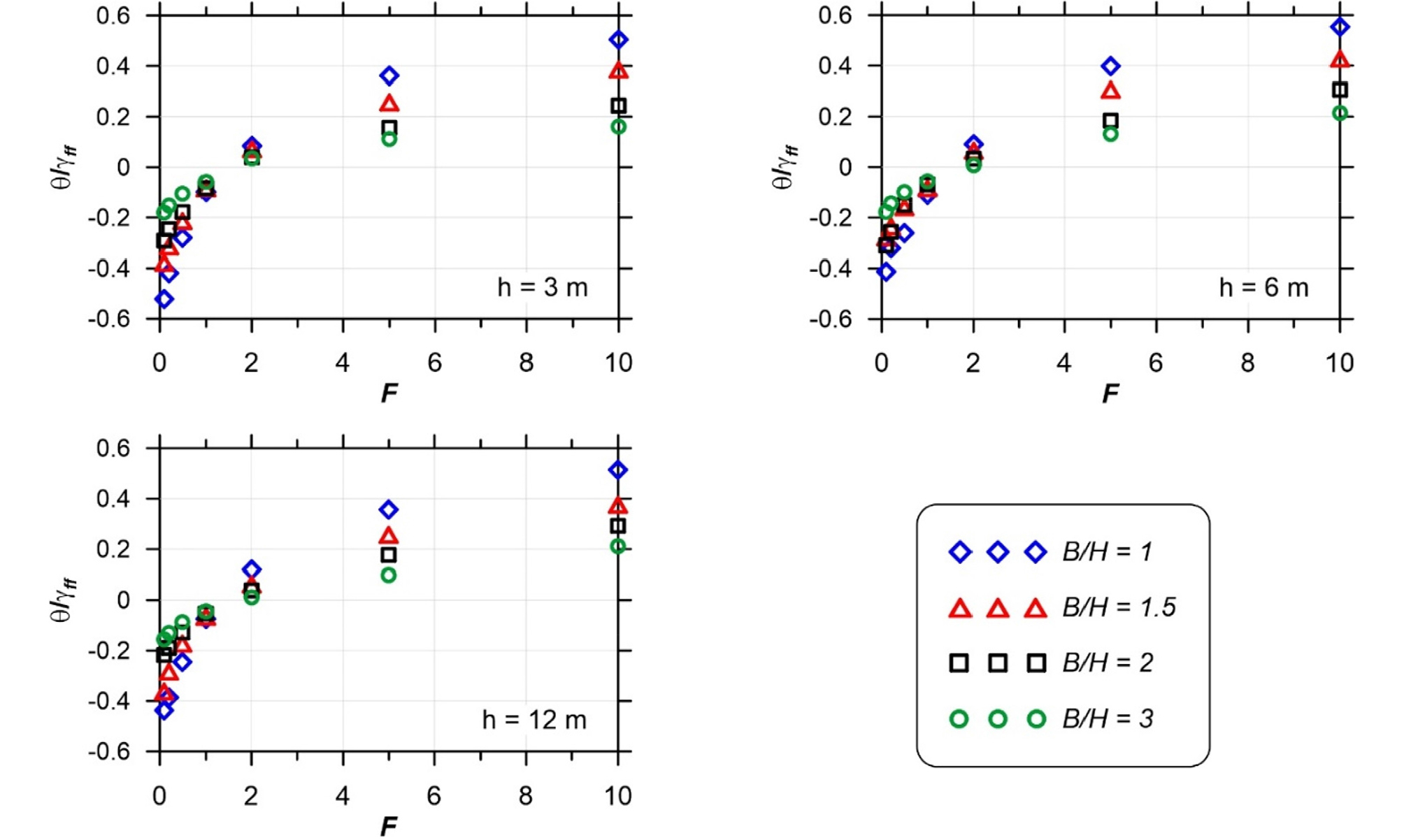
Rocking rotation (θ) representing for the rocking response of the tunnel during seismic shaking, was calculated as follows (Tsinidis & Pitilakis, 2018):
where ylw and yrw are vertical displacement time history of the left and right walls, respectively.
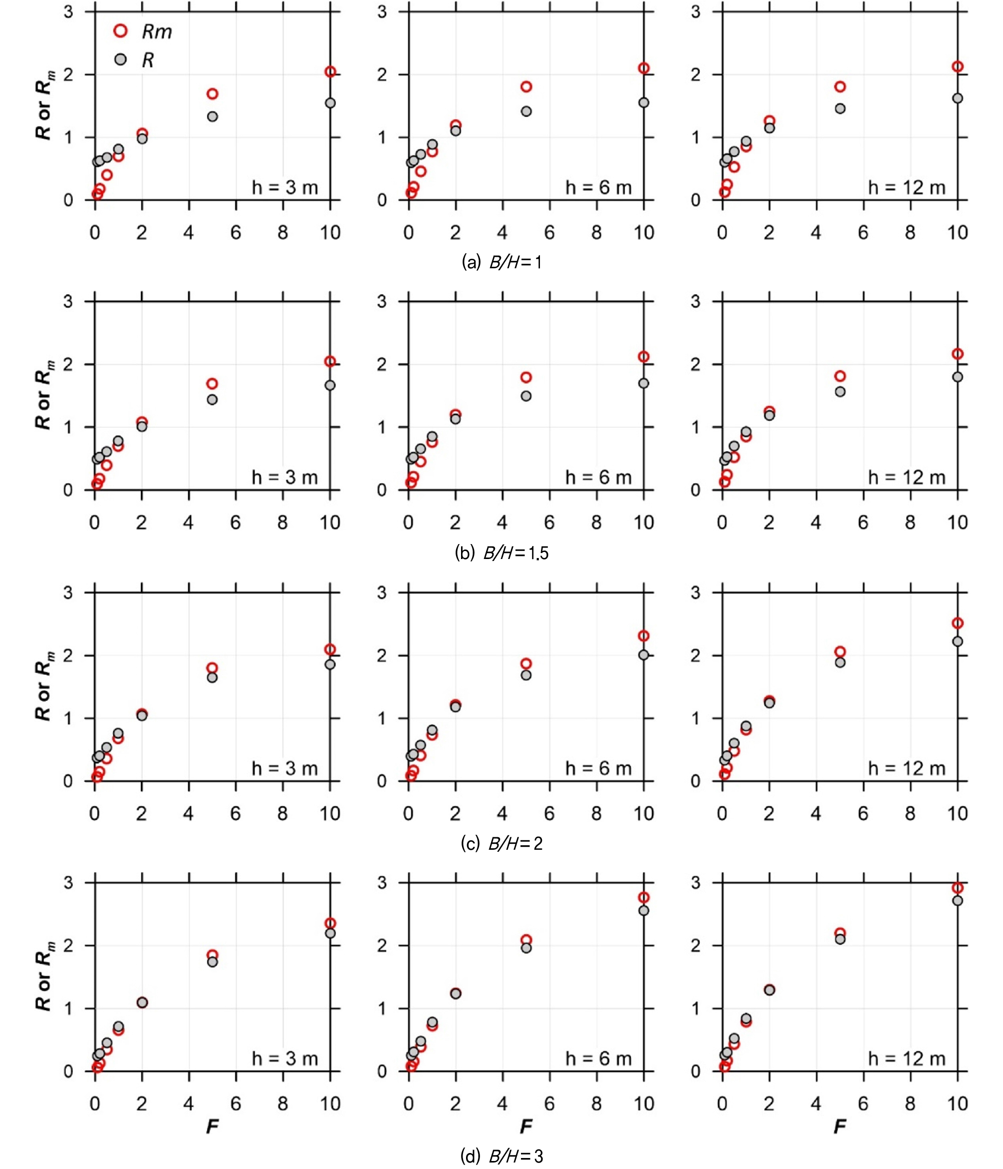
Fig. 6 presents the average F-R and F-Rm relations obtained from various soil-tunnel configurations subjected to three input motions. The differences between R and Rm for each buried depth and aspect ratio increases with the increase of the stiffness distinction of soil and tunnel (i.e. R > Rm for rigid tunnels and R < Rm for flexible ones). In contrast, the difference decreases with the increase of the aspect ratio. The cause of the deviation is due to the rocking response of the tunnel during seismic shaking. Fig. 7 presents the normalized rocking rotation with respect to the free-field shear strain (θ/γff). The physical meaning of positive and negative θ/γff values are that the tunnels are assumed to rotate the counter-clockwise for the flexible ones and the clockwise for the rigid ones. As can be seen from the figure, similar trends to deviation between R and Rm are observed. The rocking response increases with the increase of the difference of stiffness between soil and tunnel. Regardless of the flexibility ratio, the rocking response decreases with a larger aspect ratio of the tunnel section. Tunnels that equal stiffness with the surrounding ground (F = 1) experience a couple racking-rocking response (θ/γff ≠ 0), not a pure racking (θ/γff = 0) as for the case of no-slip conditions (Tsinidis & Pitilakis, 2018). These results further support the recent findings of Tsinidis & Pitilakis (2018). Generally, pure racking occurs when a flexibility ratio is approximately equal to 1.5. This finding may be somewhat limited to soil-tunnel configurations used in this study. The buried depth has a slight effect on the rocking response and the deviation between R and Rm.
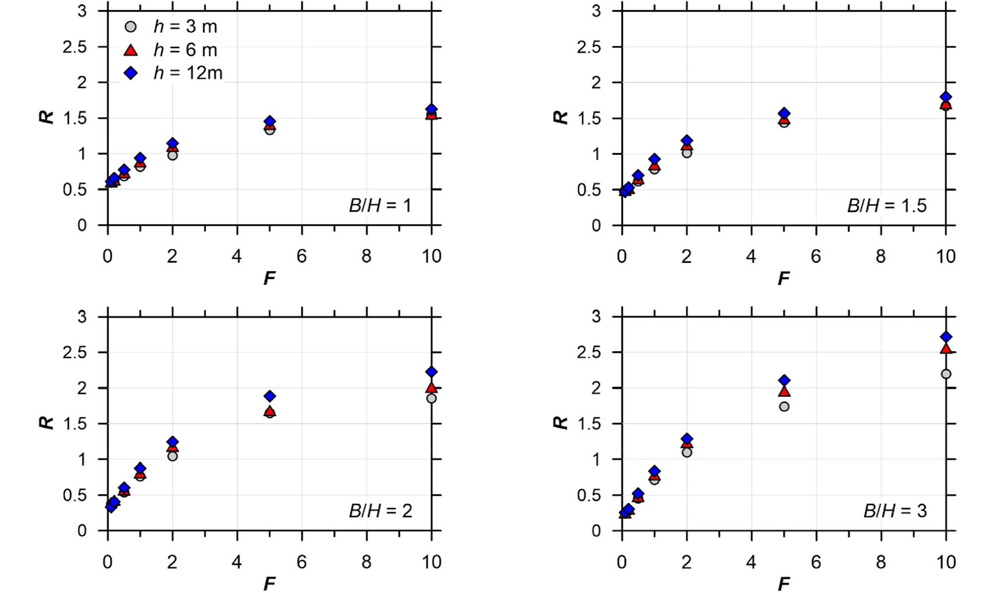
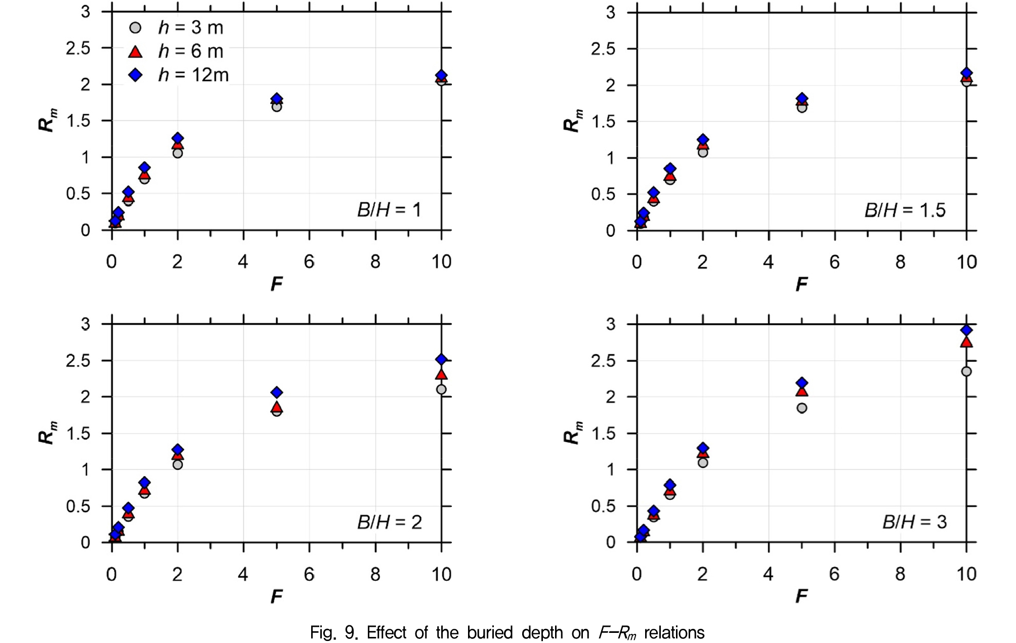
3.2 Effect of buried depth
Several attempts have been made to investigate the effect of the buried depth on the seismic response of tunnels (Chen et al., 2012; Cilingir & Madabhushi, 2011a, b; Debiasi et al., 2013; Hashash et al., 2001; Liu & Song, 2005; Ma et al., 2018; Sharma & Judd, 1991; Tsinidis & Pitilakis, 2018; Wang, 1993). The response mainly focused on risk, internal forces, stresses, and horizontal deformation of tunnel structures. Few studies have investigated the effect of the buried depth on flexibility-racking ratio relations and its understandings have been different. Specifically, Debiasi et al. (2013) and Tsinidis & Pitilakis (2018) concluded that the racking ratio reduced lightly for increasing buried depth. However, Wang (1993) obtained the opposite trend.
In this study, the effect of buried depth on R and Rm is presented in Fig. 8 and Fig. 9. As can be seen from the figures, regarding F and B/H, R and Rm increase with the increase of buried depth. A possible explanation for this might be that assumed shear wave velocity increases along with the depth, therefore soil stiffness also increases with the depth. In fact, the racking ratio increase with the increase of soil stiffness (or flexibility ratio). This reason is consistent with that assumed in earlier studies (i.e. constant shear wave velocity profile with the depth in (Debiasi et al., 2013; Tsinidis & Pitilakis, 2018) and increased one with the depth in (Wang, 1993). Moreover, the effect of the buried depth is more clearly as the aspect ratio increases.
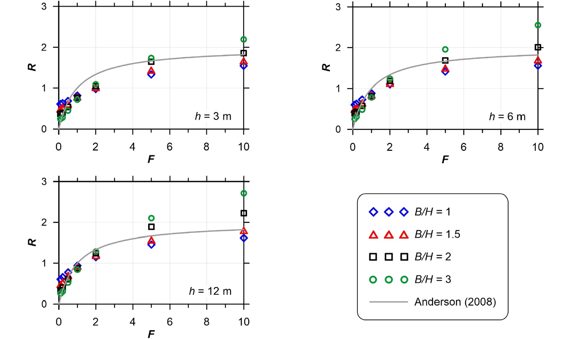
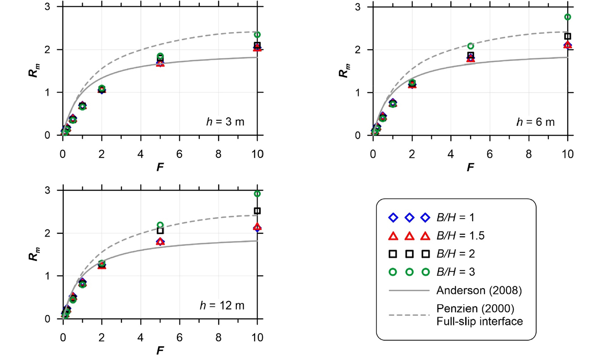
3.3 Effect of aspect ratio
Historically, the effect of the aspect ratio on F-R relations have not been considered (Anderson, 2008; Penzien, 2000; Wang, 1993). Recently, Tsinidis & Pitilakis (2018) showed that the racking ratio increases with the increase of the aspect ratio obtained from simulations using a visco-elastic soil model and no-slip condition between soil-tunnel. In this study, another view of the numerical model that considering nonlinear soil behavior, friction interface between soil-tunnel was used to investigate the effect of the aspect ratio. The numerical results are shown in Fig. 10 and Fig. 11. Generally, a similar trend to Tsinidis & Pitilakis (2018) was observed, i.e. R and Rm increase with the increase of the aspect ratio. The difference is more clearly for the flexible tunnel. The reason for this can be attributed to the effect of overburden pressure on the geometrical nonlinearity of the tunnel during seismic shaking. The geometrical nonlinearity is sensitive to soil behavior model, aspect ratio, buried depth, and tunnel lining thickness (Tsinidis & Pitilakis, 2018). The higher aspect ratio results in a higher overburden pressure on the tunnel structure which in turn causes more deformed structure. Further analyses without considering gravity effect were performed to extract F-Rm relations for the case of B/H = 1 and 3 at the buried depth h = 12 m, as shown in Fig. 12. Indeed, it can be seen from the figure that the effect of the aspect ratio on F-Rm relations is minor. Fig. 10 plots F-R relations against well-known empirical one proposed by Anderson (2008) to further support the findings of Hashash et al. (2010). Regardless of the flexibility ratio, numerical results are either overestimate or underestimate the racking ratio compared to Anderson one (Anderson, 2008). Fig. 11 compares the relations of F-Rm in this study with those of Penzien (2000) and Anderson (2008). It reveals from the figure that, Anderson relations overestimate the racking ratio for the case of soft to moderately stiff soil, whereas underestimating for the case of moderately stiff to stiff soil. Interestingly, the relations proposed by Penzien (2000) provided a conservative result (except for some case with F = 10). Therefore, Penzien (2000) relations can be used for the preliminary design stage.

3.4 Proposed equations
In this section, the proposed equations for F-Rm relations are developed. Based on calculated results, a functional form according to Anderson (2008) was updated as follows:
where P1 and P2 are coefficients accounting for both the influence of aspect ratios and buried depth ratios and listed in Table 5. Also listed are the coefficients of determination (R2) for different soil-tunnel configurations. P1, P2, and R2 were calculated using a nonlinear curve fit analysis program, Origin (2016).
Table 5.
Coefficients and coefficient of determination for Rm proposed equations
4. Conclusions
A series of nonlinear dynamic analysis was performed accounting for different soil-tunnel configuration subjected to three input motions. A contact interface was used to simulate the gap and slip between soil and tunnel. The numerical model was validated against centrifuge test records. Based on the numerical results, the following conclusions are drawn:
(1) A set of F-R and F-Rm relations were developed for a wide range of tunnel sections, buried depths, and soil profiles. R and Rm increase with the increase of either the buried depth or the aspect ratio. Significant differences were found between R and Rm due to the rocking response effect.
(2) The rocking response of the tunnel section during seismic shaking was evaluated and quantified as the normalized rocking rotation to the free-field shear strain-flexibility ratio (θ/γff-F). A similar trend to the deviation between R and Rm, the rocking response increases with the increase of the difference of soil-tunnel stiffness, whereas it decreases with the increase of aspect ratio. The tunnel that equal stiffness with surrounding soil (F = 1) experienced a racking-rocking mode (q/gff ≠ 0) in the case of friction contact interface condition between soil-tunnel, not a pure racking (q/gff = 0) as for the case of the no-slip condition.
(3) Equations for computing Rm from F were proposed by adjusting the coefficients in the empirical equation of Anderson (2008). By comparing the F-Rm relations with the widely used analytical and empirical ones, it revealed that the relations proposed by Penzien (2000) provided a comparable result. It thus can be used for the preliminary design stage.
